Archive for the 'radiobox' Category

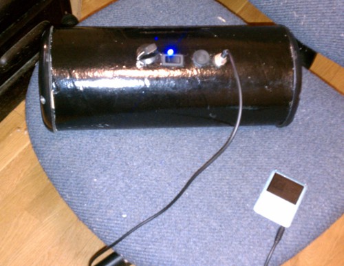
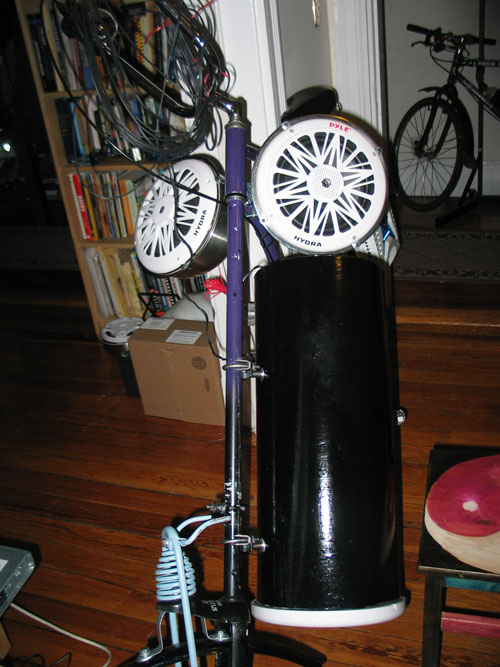
Radiobox prototype, beta version, finished

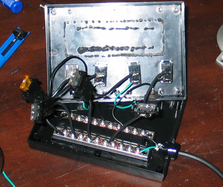
I’ve resolved a few problems with the initial design.

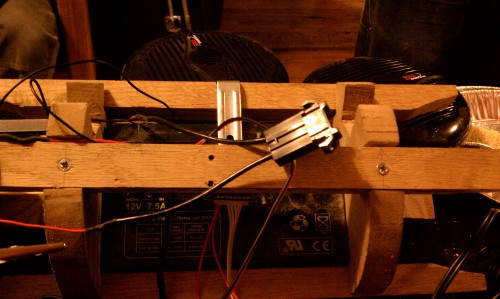
1. Added an LED power indicator light.
2. Added an ATO fuse holder instead of soldering the fuse directly to the power wires. This allows for fuse removal and replacement:

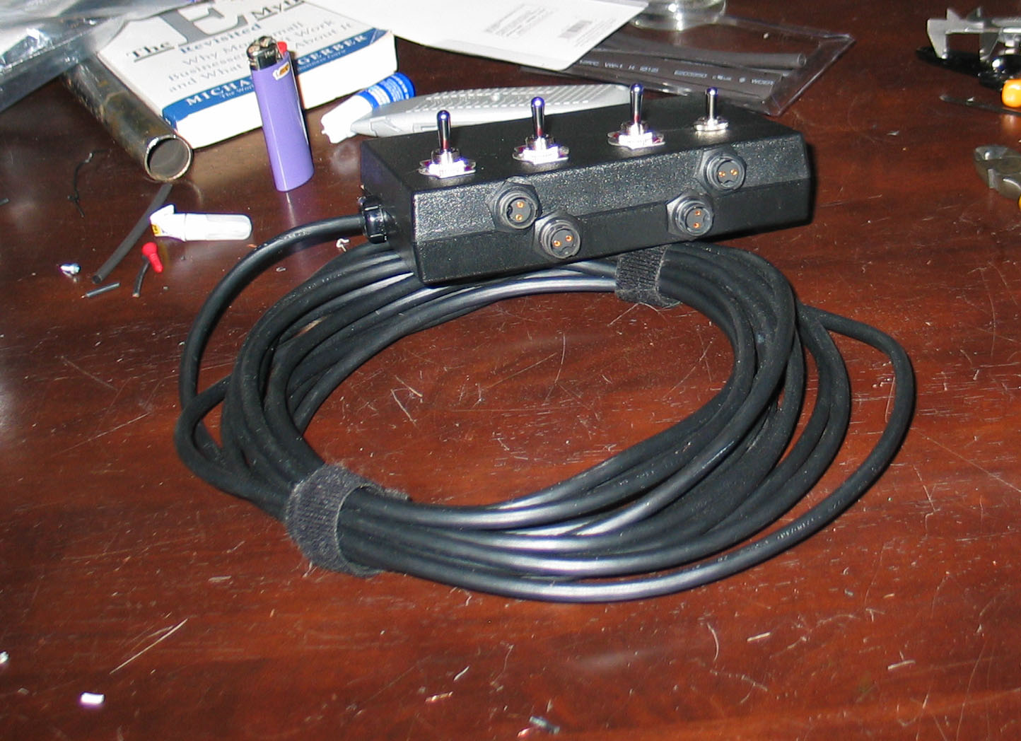
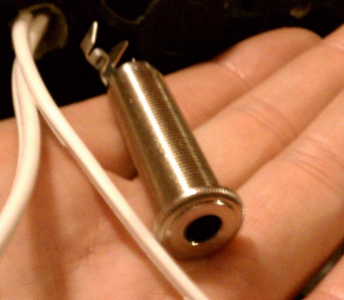
3. Added an external 1/4″ stereo jack, so that the audio cable between the amp and the iPod isn’t permanently attached to the amp. This simplifies removing the amp from the bicycle rack and makes it a modular unit without permanently attached cables dangling from it:

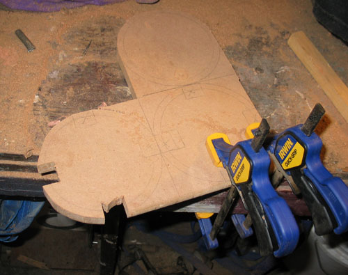
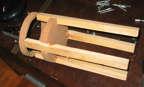
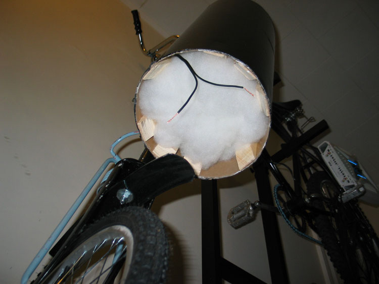
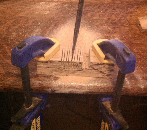
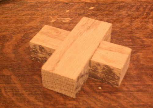
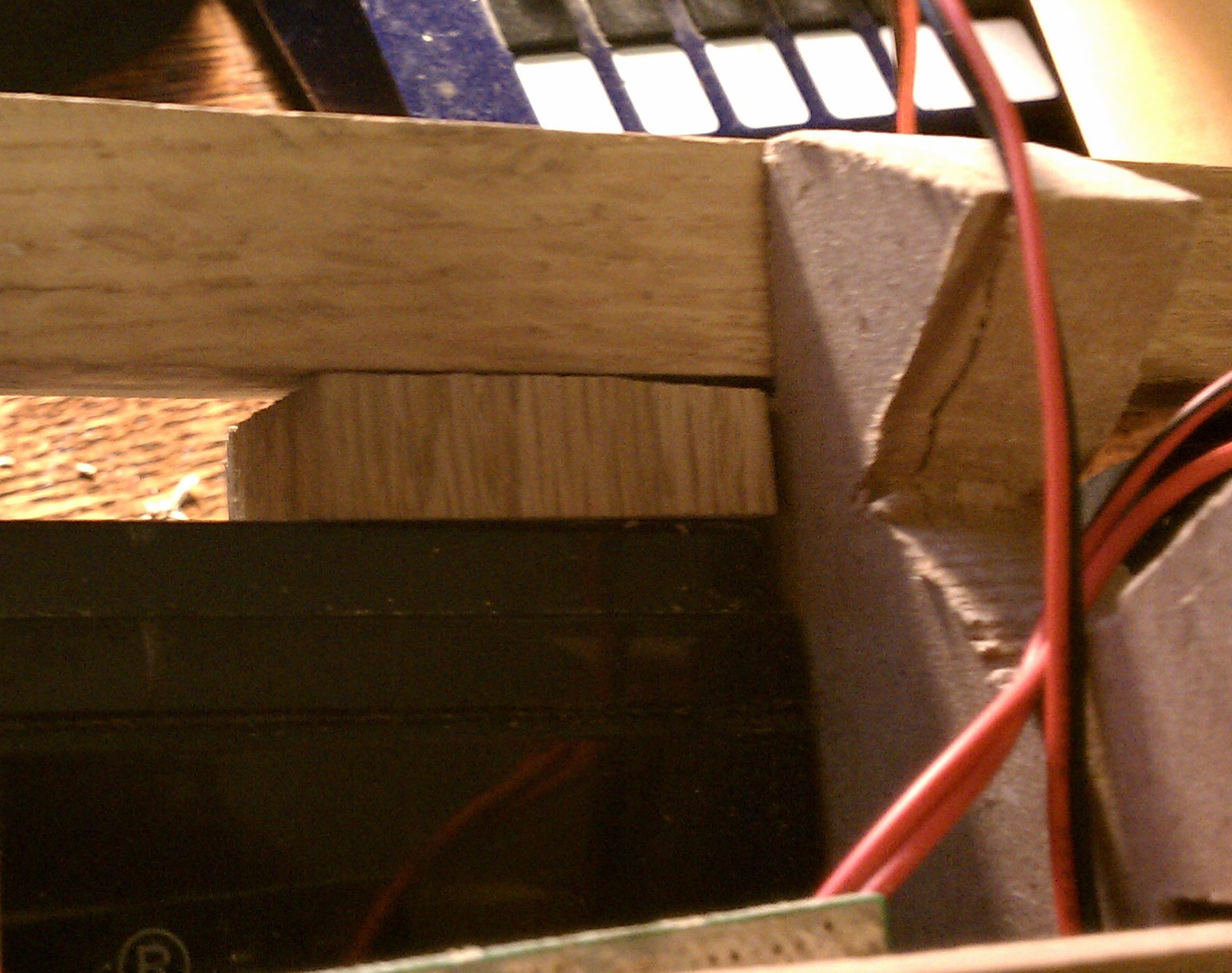
4. Replaced an internal MDF brace with a wooden cross-brace. This leaves more room for cables internally and reduces the chance that a cable will get snagged during disassembly. Sometimes it’s okay to use the wrong tools for the job — that’s a flat head screwdriver being used as a chisel:

Completed brace:

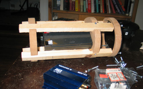
5. Replaced the jury-rigged internal battery braces with wooden block bracing. The wooden block bracing is more robust and simpler than the old metal bracket, which bent during use due to vibration:

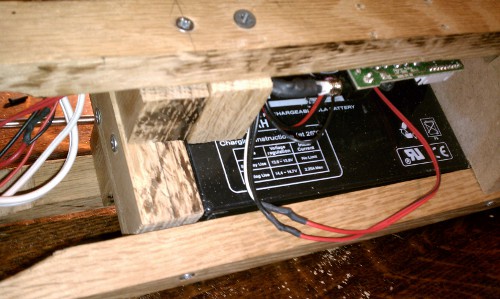
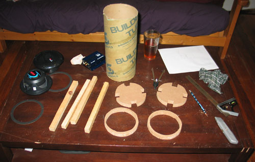
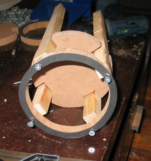
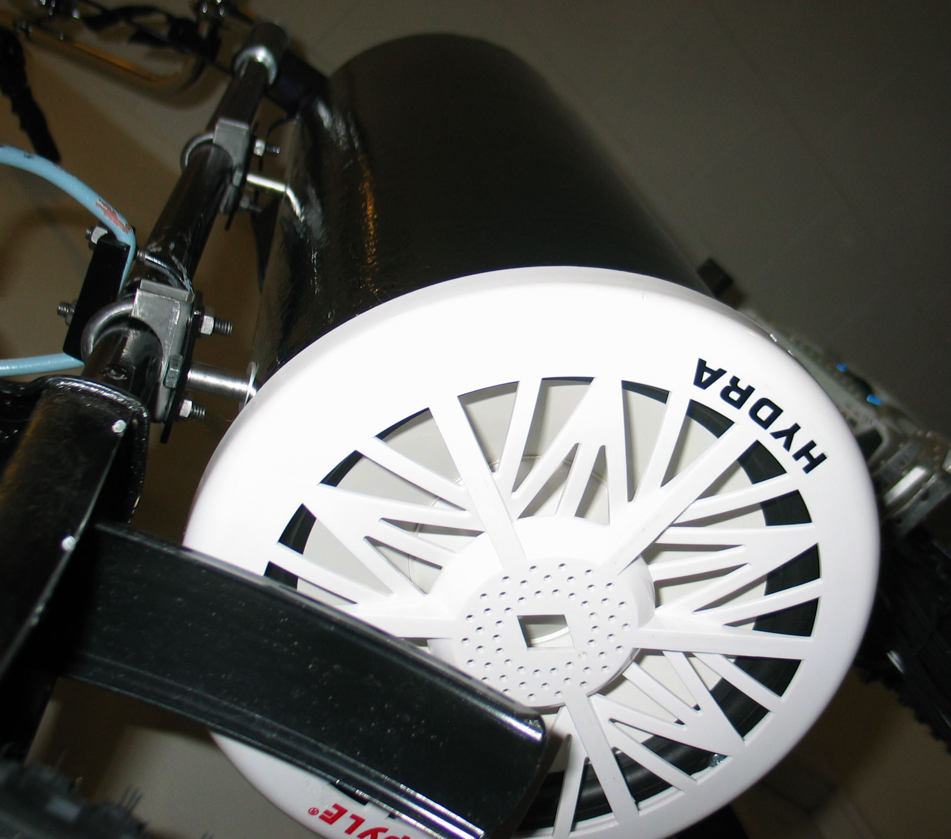
6. Replaced the internal pine bracing with oak bracing. The oak bracing is much stronger, and speakers can be directly screwed into the ends of the oak bracing. MDF is not structurally strong enough to stand up to repeated disassembly and reassembly.

This is the end point for this version of the portable radiobox. The next revision – a totally different unit – will have several improvements, which are under wraps for now!

Two Projects

I have two bicycle-related projects running simultaneously right now. The first one is a small rack-mountable radiobox, shamelessly lifted from the BikeBoomBox, which was in turn shamelessly lifted from MOSFETgrrl’s bike stereo. My goals with this radiobox are to make it easily reproducible, cheap and effective.

The basic idea is to use 6″ sonotube as a shell, build an internal frame out of MDF and pine for strength, jam a large SLA battery and an inexpensive super-efficient class T amp inside, and put marine speakers on either end. The total outlay *should* be less than $100, it should be weather-resistant, mount on a standard bike rack, accept mp3po input and be rechargeable. It can also be disassembled if necessary.

Here’s some MDF marked up with the speaker dimensions:

And in the process of being cut with a jigsaw:

MDF produces lots of nasty dust. It’s not really sawdust — it’s much finer, and is really not a good thing to breath. I tied a wet rag over my face to keep the dust out.

After an hour or so of cutting up wood, all the parts were ready for assembly:

The speakers attach at one end. A solid piece of MDF seperates the speaker area from the battery compartment:

Here’s an end shot with foam padding attached where one of the speakers will sit:

And here is the 7.5 Ah SLA battery fitted inside:

Next I need to install the class T amplifier, which just arrived from parts-express this week. Thanks to Pywaket for introducing me to this neat device.


I’ve also been working on a swingbike. Designing a strong center joint that can be disassembled for servicing has been challenging, but with Skunk’s high quality welds in place I think this iteration is going to work out:

The top piece will get bolted in with a thick hardened steel bolt. Here’s a top-down view of the joint, showing the bolt hole:

And a side view of the two connected frames. I’m going to use different handlebars ultimately:

It still needs a lot of work: painting, rear wheel, new cranks and chainring… but the hard part is finished!

Radiobox progress

I haven’t been blogging lately, but that doesn’t mean I’ve been idle. I’m working on adding a radiobox onto ARP Synesthesia, and also starting to plan out my next builds — swingbikes! I’m pressed for time right now, but here are a few photos.

I managed to mount the subwoofer to the front fork using U-bolts and by cutting a flat mount out of steel stock. This taught me the value of a sharp hacksaw blade, and its effectiveness over an angle grinder. The angle grinder is an excellent brute force weapon, but the hacksaw blade excels at fine work. Anyhow, I’m stuffing the sub enclosure with polyfill in order to deaden the sound — lots and lots of polyfill:

The inside of the subwoofer enclosure was liberally sprayed with spray adhesive — nasty stuff — and I jammed the polyfill inside the enclosure:

Once the polyfill was loaded, the next challenge was installing the woofer itself. That went well — I drilled pilot holes into the wooden braces inside the enclosure. Amazingly enough, the wooden braces matched up well with the locations of the screw holes on the woofer. Score one point for measuring ahead. However, the grill cover for the woofer, which is supposed to pop in and turn into place, wouldn’t fit in place because the enclosure wasn’t perfectly round. I ended up using some ratcheting straps — come-alongs, basically — to force the grill in position and pop it in place. It took a significant amount of pressure; I hope that I don’t have to open the sub box up anytime soon, since it’s going to be just as difficult to remove. Here’s the grill, installed:

Blam.

I also found a good spot to mount the speakers. The front part of the top tube of this frame turned out to be an ideal place. They’re not on the handlebars, so they don’t affect steering, and they’re towards the front, which will help counterbalance the warp core when it’s installed:

Finally, I started looking at this pile of electronic doodads and thinking about making them into something cohesive:

The electrical bus box just came together reasonably quickly. With several false starts, but hey, it worked out well in the end. The input is through a vaccuum cleaner cord and will be fused close to the positive terminal of the warp core. There are four outputs — one fused at 20 amps, for the stereo system amplifier, and three more with 2 amp fuses for lighting. Here’s a shot of the inside, showing the electrical bus and in-line fuses:

And here’s the electrical bus system, completely assembled:

This will mount to the handlebars for easy access. An iPod can be strapped to the surface of the bus box to provide sound input. Next tasks are to complete the remaining electrical and audio cabling, and then route the cables. Woot!

Next Page »